The Tesseract
The tesseract, or 4D cube, is perhaps the most well-known of all the 4D objects. It is known by many names, among which are the 4-hypercube, the 8-cell, the 4D measure polytope, and the tetracube. It is bounded by 8 cubes, 24 squares, 32 edges, and 16 vertices. Its many names describe its different special properties. It has been the subject of several stories, such as Robert A. Heinlein's And He Built a Crooked House. It has also been the subject of countless 4D wireframe rotation programs, screensavers, and Java applets.
The name “tesseract” comes from the Greek τέσσερεις ἀκτίνες, meaning “four rays”, referring to the four mutually perpendicular directions on which it is based.
Construction
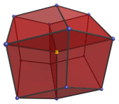
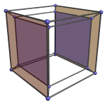
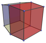
There are several ways of constructing the tesseract. The simplest way is to extrude the 3D cube along the W-axis. The following oblique projection of the tesseract underlines this method of constructing the tesseract.
The red cube shows the starting 3D cube, and the blue cube shows the endpoint of the extrusion. The yellow faces trace out the path of the extrusion. They actually form 6 other cubes, which are generated by the extrusion of each of the 6 faces of the original cube. So the tesseract in fact consists of eight cubes. These 8 cubes form its outer boundary.
Cell-first Projections
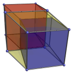
The difficulty with the above image is that there are too many intersecting surfaces, so it is difficult to discern the 8 constituent cubes. The following diagram tries to correct this defect by using a perspective projection instead:
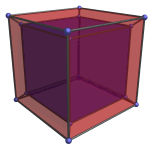
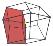
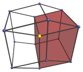
In this image, the blue “inner” cube is actually the same size as the red “outer” cube, but it appears to be smaller because it is farther away along the W-axis. Between the inner and outer cubes are 6 frustums that are actually the other 6 cells, as shown by the following images:
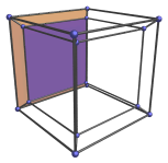
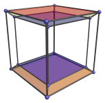
These 6 frustums are actually regular cubes; but they appear distorted into frustums because they are seen at an angle. Furthermore, all 8 cubes lie on the outer boundary of the tesseract. Even though it appears that the inner cube is on the “inside” whereas the outer cube is on the “outside”, they actually both lie on the outside of the tesseract, on two opposite sides. The following animation shows what happens when we rotate the tesseract in the XW plane.

The red and blue cells appear to be deforming inside-out and engulfing each other, but this is only an artifact of projection into 3D. In reality, they are perfectly regular cubes, two opposite cells of the tesseract, and neither deform nor touch each other as they rotate through 4D space.
Hidden Surface Removal
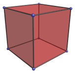
One thing that is often neglected to be mentioned when such wire diagrams of the tesseract are presented is the fact that they represent projections of the tesseract without the removal of hidden surfaces. This is like showing the rotation of the wireframe of a 3D cube, where you can see through its faces and see what is on the other side of the cube. While this is useful in seeing the entire structure of the tesseract, it sometimes gives too much detail and becomes confusing. The following images try to complement the picture by showing projections of the tesseract where obscured 4D surfaces are not shown.
For example, when viewed from the angle that corresponds with the cube-within-a-cube image shown earlier, the tesseract in fact appears as a simple 3D cube:
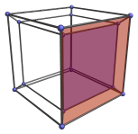
When rotated 45 degrees in the XW plane, the tesseract appears as follows:
Only two cells are visible because the rest are obscured behind them in the 4th direction.
Vertex-first projection
Another fact that is often neglected when tesseract projection images and
diagrams are shown is that projections such as the cube-within-a-cube actually
view the tesseract from a “flat” angle, akin to looking at a 3D
cube directly at one face, or perhaps at an edge, and seeing only two faces at
a time. Just as we intuitively imagine the 3D cube from an angle such that we
can see three of its faces at a time, so a more intuitive
angle
of looking at the tesseract is from an angle where we can see four of
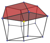
its cells at once. The following image shows one such view of the
tesseract.
The 3D surface of this projection is a rhombic dodecahedron, a 12-faceted polyhedron where each face is a rhombus. The nearest vertex to the 4D viewpoint is the one in the center of the projection, highlighted here in yellow. The four cells of the tesseract visible from this angle are shown below:
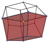
The other four cells of the tesseract are behind these four in the 4th direction, so they are not visible here.
Geometrical Properties
The tesseract belongs to the family of n-dimensional hypercubes, also known as measure polytopes (because they constitute the unit by which n-dimensional space is measured). Its dual is the 16-cell. The coordinates of an origin-centered tesseract with edge length 2 are all permutations of sign and coordinates of:
- (1,1,1,1)
Interestingly, not only is the 16-cell its dual, but also its alternation. This property is peculiar to 4D; in 3D, the alternated cube is the tetrahedron, and in 5D, the alternated cube is a semi-regular polytope known as the demipenteract. This property is useful for deriving a coherent indexing of the 24-cell, which allows us to construct the 600-cell using the snub 24-cell as an intermediate.


