The Cubical Cylinder
Construction
The cubical cylinder, or cubinder for short, is one of the ways to generalize the 3D cylinder to 4D. This object can be constructed by extruding a 3D cylinder along the W-axis by a unit distance. The following oblique projection of the cubinder demonstrates this extrusion:
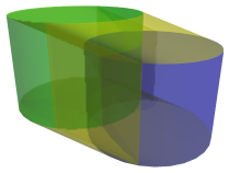
The green cylinder represents the starting point of the extrusion, and the blue cylinder represents the endpoint. During the process of extrusion, the circular lids of the green cylinder are themselves extruded into two new cylinders, as highlighted in cyan below:
These two additional cylinders appear to be distorted here, but this is an artifact of the oblique projection. In 4D, they are regular cylinders identical to the green and blue cylinders in the previous image.
Perspective projections
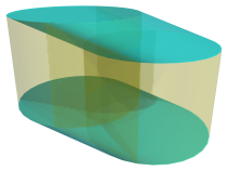
The following is a perspective projection of the cubinder:

The inner cylinder is actually the same size as the outer cylinder, but appears smaller in perspective because it is farther away. Furthermore, there are two frustums, an upper frustum and lower frustum, connecting the inner cylinder to the outer cylinder, as shown in cyan in the following image:

These frustums are actually themselves regular cylinders; but they appear as frustums because they are seen at an angle. They are the two extra cylinders generated by the extrusion of the lids of the original cylinder.
The next diagram shows another perspective projection, this time with the cubinder rotated 45 degrees in the ZW plane.
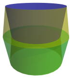
Here, it is more apparent that the cubinder consists of four 3D cylinders joined at their circular ends. The blue cylinder has rotated upwards a bit, and the green cylinder has rotated downwards. A yellow cylinder joins the top lid of the blue cylinder to the green cylinder, and a fourth cylinder joins the bottom of the blue cylinder to the bottom of the green cylinder.
There is another shape that forms the boundary of the cubinder: a square torus that lies between the rounded sides of the four cylinders. It is shown in the next image:

We have cut out a section of the torus so that its cross-section is visible. Although it appears to have a thin diamond-shaped cross-section, this is actually an artifact of projection; in 4D, its cross-section is square. This torus is formed by the extrusion of the round side of the original cylinder.
These projections do not have hidden surfaces removed, so that the whole structure of the cubinder is more apparent. However, a 4D being looking at the cubinder would not see the entire structure simultaneously. The inner cylinder in the second diagram would not be visible, for example, and neither would the two inner cylinders in the second diagram. The following image shows the cubinder with hidden surfaces removed, viewed cylinder-first:

Only the green cylinder is visible here, because the other surfaces lie behind this cylinder in the fourth direction and are obscured by it.
The next image shows the 45° angle view of the cubinder, with hidden surfaces culled:
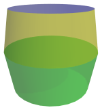
Here, we see the two frustum-shaped volumes, which are really cylinders in 4D. The bottom frustum is the green cylinder in the previous image, and the blue lid of the blue cylinder is seen. The blue cylinder itself lies behind the yellow cylinder in the fourth direction, and is not visible here.
Parallel projection
Now, the reason for the cubinder's name is that one of its possible parallel projections is the cube:
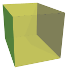
The blue and green cylinders have been collapsed into squares here because they now lie at a 90° angle to the 4D viewpoint. Their circular lids project to the top and bottom edges of the blue and green faces. This projection shows how the two yellow cylinders, which are projected to the top and bottom squares here, trace out the extrusion from the green cylinder to the blue cylinder. The front and back square faces of this cube are the limb of the square torus that wraps around the cubinder.
Properties
The square torus bounding the cubinder forms a circular surface on which the cubinder may roll. Although there are 4 cylinders bounding the cubinder, they are in fact flat in 4D. One may understand this by analogy with a 3D cylinder: the two circular lids are round in 2D, but flat as 3D surfaces. When a cylinder rolls, it does not roll on its lid, but on the curved surface that wraps around the circular edge of the lid. In the same way, the cylindrical surfaces on the cubinder all lie in flat hyperplanes, and the cubinder cannot roll on those surfaces. It is the square torus, which wraps around the circular boundaries of those four cylinders, that the cubinder may roll on. This rolling covers only the space of a line.


